
DIN Rail Mounting Terminals - Technical Reference
21st Jan 2020
Wire Termination
Systematic wiring in a panel board requires a layout of properly selected terminal blocks. In normal cases, you should assign one wire per clamping unit of a terminal block thus, simplifying the task of identification of each circuit.
Our screw clamp terminal blocks can accommodate wires one size higher than the rated cross section. They can also take two wires one size smaller than the rated cross section.
If, however, two wires are connected to one clamping unit of a screw clamp terminal block, care must be taken to ensure that the total current assigned to the two wires does not exceed the continuous rating of the terminal block.
For 'screwless' spring clamp terminal blocks, special care must be taken that only one wire must be connected per clamping unit.
The relevant standard, IEC 60947-7-1, section 4.3.5 states that for terminal blocks with a rated cross section from 0.2 sq. mm to 35 sq. mm. (both inclusive), the manufacturer shall specify the range and number of the rated cross section. The conductor can be rigid (solid or multi strands) or flexible (fine strands), these values can be found in the product related technical data.
Our feed through terminal blocks are designed to allow copper wires to be connected without any special preparations such as soldering the individual strands of wire or using cable lugs / ferrules. However, wires requiring special preparation can also be used in our terminal blocks, as per IEC 60947-7-1.
For connecting aluminium wires, special care must be taken while stripping the insulation from the wires. It is strongly recommended to use ferrules and lugs when connecting flexible aluminium wires. Once the wire has been stripped of its insulation to the recommended length, it should be coated with acid and alkaline free petroleum jelly and be screwed into the terminal immediately. This procedure must be followed each time an aluminium wire is to be disconnected and reconnected.
In applications where connections have to be changed frequently, it is recommended to use lugs / ferrules / cable sockets to avoid fracturing of individual wires.
Wire Connection Method
Screw Clamp Connection

The screw clamp connection is the most popular method of wire termination. It offers distinct advantages over the other wire termination methods:
- Suitable for all cross-sections and types of wires
- Wires can be connected without any special preparation
- Provides vibration resistant connection
- Simple connection and disconnection of wires with the aid of an ordinary screw driver (see Fig.1)
- The cold forged rolled threaded screws provide high tightening torque
The steel clamping screw produces high contact force while the steel clamping yoke transmits this force by pressing the conductor against the current bar. The conducting medium within a terminal block is the current bar, which is made from electrolytic copper or 63 / 37 brass and tin plated. The tin plating on the current bar ensures excellent continuous contact and provides good protection against corrosion. Even the best electrical conductor materials are worthless without the required contact force to press the connected wire to the contact surface on the current bar. Due to this the clamping yokes and screws are made of steel. The steel parts are zinc plated and additionally chromate passivated in order to achieve the highest degree of corrosion resistance.
When the clamping screw is tightened, the clamping yoke is pulled upwards, pressing the wire against the current bar. The clamping yoke and current bar are serrated. The serrations of the current bar cut through the oxide skin of the wire on tightening, thereby providing many contact lines. The serrations of the clamping yoke also improve the gripping of the wire. When the wire is tightened, the clamping pressure pulls the top threaded surfaces of the yoke exerting a high locking action on the clamping screw (see Fig. 2).
Changes caused by temperature variations, if any, are effectively equalised by the elasticity of steel, providing excellent vibration resistance.
Large pressure areas on the current bar and the clamping yoke prevent notching, which otherwise could lead to possible wire fracture. The clamping yokes come in different sizes and shapes to accommodate wires of different cross sections. A flat clamping area ensures safe gripping of wires of smaller cross sections. The flange / tail of the clamping yokes prevents incorrect entry of the wires underneath the yokes.


The following characteristics make the screw clamp connection user friendly, versatile and sturdy:
- Strong contact force which makes it absolutely gas tight
- Very low contact resistance
- Excellent vibration resistance preventing loosening of screws
- Reliable electrical and mechanical connection
- Ease of handling
Click here for our range of Screw Clamp Terminals
Cable Lug Connection

This method of wire termination is preferred for connections that are subject to very severe vibrations. The wire is crimped to a ring / fork type ferrule and is screwed on to the flat current bar of the terminal block.
Spring Clamp Technology

The more recently introduced screwless spring clamp connection is as versatile as the screw clamp connection. In this type of a connection, the wire is held against the electrolytic copper current bar directly by a pre-stressed spring clamp. The spring is operated by using a flat head screw driver to open the spring clamp and provide access for the wire. The inserted wire becomes clamped on to the current bar by the spring force as soon as the screw driver is removed. The high quality stainless steel spring clamp ensures a good connection to the wire with minimal contact resistance. The electrical and mechanical quality of the wire connection is maintained by the high quality rust proof spring clamp. Only one wire per clamp must be terminated.
 DIN-Rail mounting terminal")
The following are the characteristics of Spring Clamp Connection:
- Easy to operate, versatile and vibration proof
- Minimal contact resistance because of a gas tight connection made possible by the high quality stainless steel spring clamp
- Fail proof / safe, maintenance free connection
- The surface treated (tin plated) electrolytic copper current bar ensures oxidation free contact
Click here for our range of Spring Clamp Terminals
Cable Lug / Bus Bar Connection
 Terminal for Fork and Ring Ferrules")
This type of connection is preferred for wires of larger cross sections. The conductor is fitted with a lug and bolted on to the flat current bar. This method is also ideal for connections subject to very severe vibrations.
Tab Connection

Quick connect tab connections are preferred in applications where the connected wire needs to be frequently connected and disconnected. The wire is crimped to a quick connect tab ferrule and pushed on to the terminal block.
Click here for our range of Tab Connection Terminals
Solder Connection

Solder connections are suitable for wires having a cross section up to 2.5 sq. mm. In this type of connection, the wire is soldered to a solder lug. If done professionally, soldering can provide a good electrical connection.
Wire Wrap Connection

This type of connection is suitable for connecting a thin solid wire. The wire is wrapped to a square pin provided in the terminal block. A special tool is required for wrapping the wire to the square pin.
Wire Tightening
The design of our screw camps / cable lug system ensures vibration proof positive connection wires at the recommended torque values. However, our terminal blocks can withstand torque levels in excess of the recommended torque values. The terminal block clamping parts when tightened within the torque range ensure optimum performance as given below:
- The voltage drop (contact resistance) is well below the specified limits
- The wire gets clamped perfectly to form a gas tight connection
- The clamping yoke does not get damaged mechanically. The tightening torque according to IEC 60947-7-1 table 4, is the safe limit of torque which guarantees successful clamping of the connected wire.
Our terminal block tightening torque data is given in the respective product pages and data sheets.
All of our terminal blocks are designed to function with rated wire sizes as per their respective AWG (American Wire Gauge) or Metric size/system. The terminal blocks are tested for gauge insertion as per VDE 0660.
Tightening Torque for Screw Clamp Terminal Blocks
| Terminal Blocks | Thread Size of Fastener | Recommended Torque Value |
| TtecCTS2.5UN / TtecCPT(M) / TtecCPT5 | M2.5 | 0.4Nm |
| TtecCTS2.5(M) / TtecCMST1 / TtecCMST2 | M2.6 | 0.4Nm |
| TtecCTS2.5 / TtecCMT4 / TtecCMB4 / TtecCDL4U / TtecODL4U / TtecCGT4U / TtecCTS4UN / TtecCTS4SC / TtecCSTSB3 / TtecCSFL4U / TtecCSDL4U / TtecCKT4U / TtecCPT7.5 / TtecDDFL4U / TtecDDFL4U(E) / TtecDDFL4U(E)LR / TtecCMC1-2 / TtecCMC2-2 | M3 | 0.5Nm |
| TtecCTS6 / TtecCTS6SC / TtecCTS6U / TtecCSFL6U / TtecCENC4 | M3.5 | 0.8Nm |
| TtecCTS10/10U / TtecCTS16/16U / TtecCSTSN4/B4 / TtecCDTTS / TtecCTS10SC / TtecCGT10U / TtecDDPT / TtecCDTTU / TtecCSTSN4U / TtecSTH4 | M4 | 1.2Nm |
| TtecCTS25U / TtecCSTSB5 / N5 / N5(15) / RN5 / N5U / TtecCENC16 | M5 | 2.0Nm |
| TtecCTS35 / TtecCTS35U / TtecCENC35 / TtecCGT35U / TtecCSTSN6U | M6 | 2.0Nm |
| TtecCTS35L/35LS / TtecCSTSRN6 / TtecCSTSN6 | M6 | 2.8Nm |
| TtecCTS70L/70LS | M8 | 6.0Nm |
| TtecCTS95L/95LS | M10 | 10.0Nm |
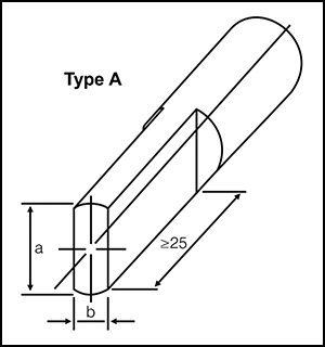
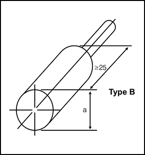
Conductor Cross-section and Gauges
| Flexible (sq.mm) |
Rigid (solid or stranded) (sq.mm) |
Gauge Type A | Gauge Type B | Permissible Deviation for a and b |
|||
| Marking | Diameter a (mm) |
Width b (mm) |
Marking | Diameter a (mm) |
|||
| 1.5 | 1.5 | A1 | 2.4 | 1.5 | B1 | 1.9 | 0 / -0.05 |
| 2.5 | 2.5 | A2 | 2.8 | 2.0 | B2 | 2.4 | 0 / -0.05 |
| 2.5 | 4 | A3 | 2.8 | 2.4 | B3 | 2.7 | 0 / -0.05 |
| 4 | 6 | A4 | 3.6 | 3.1 | B4 | 3.5 | 0 / -0.06 |
| 6 | 10 | A5 | 4.3 | 4.0 | B5 | 4.4 | 0 / -0.06 |
| 10 | 16 | A6 | 5.4 | 5.1 | B6 | 5.3 | 0 / -0.06 |
| 16 | 25 | A7 | 7.1 | 6.3 | B7 | 6.9 | 0 / -0.07 |
| 25 | 35 | A8 | 8.3 | 7.8 | B8 | 8.2 | 0 / -0.07 |
| 35 | 50 | A9 | 10.2 | 9.2 | B9 | 10.0 | 0 / -0.07 |
| 50 | 70 | A10 | 12.3 | 11.0 | B10 | 12.0 | 0 / -0.08 |
| 70 | 95 | A11 | 14.2 | 13.1 | B11 | 14.0 | 0 / -0.08 |
| 95 | 120 | A12 | 16.2 | 15.1 | B12 | 16.0 | 0 / -0.08 |
| 120 | 150 | A13 | 18.2 | 17.0 | B13 | 18.0 | 0 / -0.08 |
| 150 | 185 | A14 | 20.2 | 19.0 | B14 | 20.0 | 0 / -0.08 |
| 185 | 240 | A15 | 22.2 | 21.0 | B15 | 22.0 | 0 / -0.09 |
| 240 | 300 | A16 | 26.5 | 24.0 | B16 | 26.0 | 0 / -0.09 |
Electrical Data
Our terminal blocks are standard blocks for industries such as switchgear, distribution, machine tool controls, instrumentation installations, material handling equipment, process plants, on and offshore Installations and panel board / control panel construction.
Rated Voltage
The voltage rating of the product is assigned according to specifications related to creepage & clearance distance defined in the respective EN, VDE, UL and CSA standards, for the environmental conditions and pollution degrees as given below.
| Degree of Pollution | Creepage and clearance distances are evaluated for the following pollution degree: |
| Pollution degree 1 | No pollution or only dry, non-conductive pollution occurs. The pollution has no influence. |
| Pollution degree 2 | Only non-conductive pollution occurs except that occasionally a temporary conductivity caused by condensation is to be expected. |
| Pollution degree 3 | Conductive pollution occurs or dry, non-conductive pollution occurs which becomes conductive due to condensation is to be expected. |
| Pollution degree 4 | The pollution generates persistent conductivity caused by conductive dust or by rain or snow. |
| Rated Impulse Voltage | The rated impulse voltage of the product is the peak value of an impulse voltage with which the terminal block can be loaded and on which the creepage and clearances according to relevant standard are based. |
CTI - Comparative Tracking Index of Insulation Material
The insulation material is divided into four groups according to their CTI (Comparative Tracking Index).
Material Group I: 600 ≤ CTI
Material Group II: 400 ≤ CTI < 600
Material Group III a: 175 ≤ CTI < 400
Material Group III b: 100 ≤ CTI < 175
The comparative tracking index must be defined according to DIN IEC 112/ VDE 0303 part 1 on samples made specifically for this purpose with test solution A. The proof-tracking index (PTI) is also used to identify the tracking characteristics of materials. A material may be included in one of the four groups given above on the basis that its PTI, established by the method of IEC 112 using solution A, is equal to or greater than the lower value specified for the Insulation group.
Current Carrying Capacity of Terminal Block (DIN EN 60947-7-1/VDE 0611part1: 2000-05)
The data given below is for unprepared conductor ends without ferrules. The rated current for terminal blocks with specific functions such as fuse carriers, relays and terminal blocks incorporating electronic components is defined in our product datasheets for the item in question.
| Rated Cross Section (sq.mm) | 0.2 | 0.5 | 0.75 | 1 | 1.5 | 2.5 | 4 | 6 | 10 | 16 | 25 | 35 | 50 | 70 | 95 | 120 | 150 | 185 | 240 | 300 |
| Test Current (A) | 4 | 6 | 9 | 13.5 | 17.5 | 24 | 32 | 41 | 57 | 76 | 101 | 125 | 150 | 192 | 232 | 269 | 309 | 353 | 415 | 520 |
Current Rating with two Wire / Conductors
The total current of the two wires / conductors should not exceed the continuous current rating of the terminal block. The continuous current rating is the maximum current the terminal block can conduct 0 without a temperature rise of 45 K (as per EN standard) and 30oC (as per UL / CSA standard).
Note: For PE-Terminals only one conductor should be connected per clamping part, in accordance with installation requirement.
Terminal Block Material
Our terminal blocks are made of carefully selected materials, insulating materials, clamping and conducting metals which are all subject to strict quality control as required by the most stringent international standards.
Clamping Screws
One of the most important parts of the terminal block is its screw. The quality of the connection is highly dependent on the quality of the screw. The screw must not become damaged and should withstand a higher torque (over-torque) than stipulated in its specification. The screw should not, even at the highest stress points weld with the metal of the main thread.
Our terminal blocks employ cold forged rolled threaded steel screws. In this screw manufacturing process the material is compressed and therefore strengthened. This produces a much stronger screw than those machined via a turning process. When turned screws are cut, the material from between the threads is removed. Due to this and also the stress concentration on the neck of the screw, the turned screw is considerably weaker.
Our screws are zinc plated and chromate passivated for a good galvanic surface.
 |
 |
| Structure of a turned Screw | Structure of a rolled Screw |
Clamping Yoke
Clamping yokes are manufactured from carefully selected grades of steel to ensure high torque performance necessary for gas tight connections. The clamping components (both screws and clamping yokes) are electroplated with zinc and chromate passivated. The Zinc creates a cathodic protection system for the steel. Therefore the effect of protection against corrosion is still retained even when the plating is partially damaged by scratches or pores.
The clamping components of some of our terminal blocks are made of copper alloys. Such components are electroplated with either nickel or tin to ensure oxidation free performance.
Current Carrying / Conducting Components
The current carrying/conducting components / current bars are made of electrolytic grade copper or copper alloy to ensure very low contact resistance. The components are electroplated with tin / nickel to provide an oxidation free contact.
Insulating Material
All the live parts in terminal blocks are totally shrouded to minimize the risk of accidental contact via an engineering thermoplastic polyamide 6.6 housing.
Polyamide 6.6
Engineering thermoplastic polyamide 6.6 has excellent electrical, mechanical and chemical characteristics, even at temperature as high as 105oC. This insulating material has high mechanical strength - close to unbreakable. The polyamide 6.6 moulded housing absorbs humidity from its surroundings. However, it does not crystallise water in the plastic itself as is the case of thermosetting plastic. The H2O groups combine within the molecular structure.
Thus the moulded plastic housing becomes fracture proof and unbreakable even in sub zero temperature conditions.
We use polyamide 6.6 rated V2 according to UL 94, as it is difficult to ignite, self-extinguishing and burns only as long as there is a supporting flame. It has excellent resistance to micro organisms, bacteria, enzymes and termites. Good ageing resistance and insensitivity to ultra violet light makes it suitable for tropical and open air applications. Polyamide 6.6 also has excellent resistance to fuels, oils, fats and most common solvents like aliphatic and aromatic carbohydrates, ketones and alcohols.